
Technical Q&A's
Complete compensation for uneven movement by the Second Joint
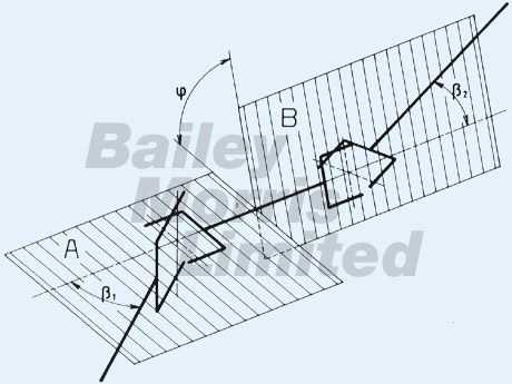
Proper connection of two universal joints in series can compensate fully for the unevenness of the movement. For example, tha advance caused by the first joint is compensated by a retard of the same order from the second joint. For this to occur, the following must be fulfilled:
1. The deflection angle of the joints must be the same.
2. The parts of the second joint must run 90° earlier or later in their deflection plane formed by the input and output shafts than the parts of the first joint. Or to put it more clearly: the forks of the centre shaft must lie in planes A and B formed by their input and output shafts at the same time.
Fig 1.
Two common applications can be derived from this general principle:
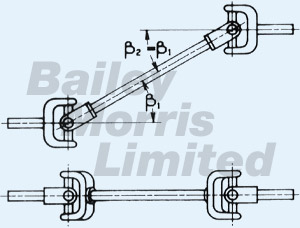
1.1 Z - Deflection
In this most common application method, the deflection occurs in one plane only (fig. 2). For complete compensation for movement, the forks of the common shaft must lie in one plane and the deflection angles must be the same.
Fig 2.
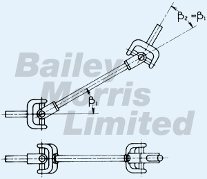
1.2 W - Deflection
Here the same applies as for Z-Deflection.
Fig 3.
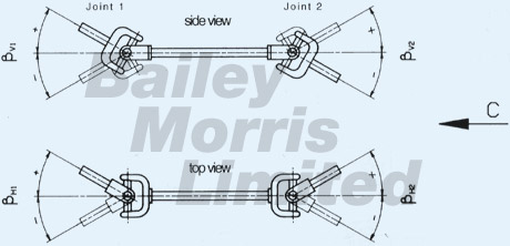
1.3 Physical Deflection
If the two shaft projections viewed from the side show a Z-Deflection and from the top a W-Deflection or vice versa, there is a physical deflection as shown in fig. 1.
The resulting deflection angles ß1 and ß2 and the twist angle of the deflection planes can be determined from the deflection angles ß1, ß2, ßH1,ßH3 of the projections in figures 4 and 5.
Fig 4.
Example (graphic process)
An arrangement as shown in Fig 6. is used. The size and direction of the twist angle must be determined.
Fig 5.
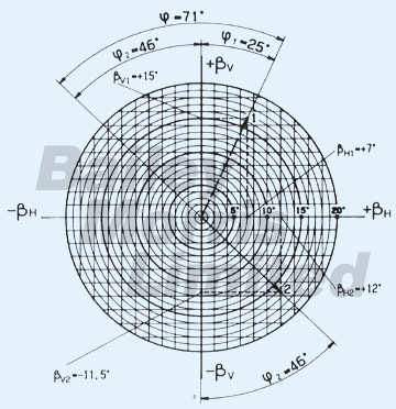
Fig 6.
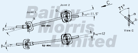
Values ßv1 = +15° and ß1H1 = + 7° are entered in the diagram (fig 5) and added geometrically. The dotted line 1 is the deflection plan of the joint 1 viewed from direction C onto the shaft. The length of the dotted line gives the resulting deflection angle ß1 = 16.5°.
The angles ßv2 = -11.5° and ßH2 = + 12° are entered in the same way and an extended line 2 gives the deflection plane of the joint 2. The length of the extended line2 gives the resulting deflection angle ß2.
The angle between the two lines 1 and 2 is the twist angle. The fork b of joint 2 lying on the common shaft must be twisted by this angle in relation to the fork a of joint 1 lying on the common shaft when viewed from direction C. In other words, by 71° counterclockwise.
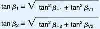
The resulting deflection angle can be calculated as follows:
and the twist angle:
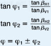
The sign must be taken from the graphic process. If the twist angle is greater than 90°, in practice the explement angle is taken.
1.4 Permitted Tolerances
If, for design reasons, complete evenness of the deflection angle is not or is not always possible, the following condition should at least be observed:
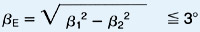
Where ßE corresponds to the deflection angle of a single joint which generates the same degree of unevenness as the propeller shaft.
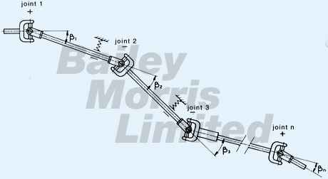
1.5 Multiple Joint Shafts
Multiple joint shafts with 3 or more joints are often used in vehicles. Then;
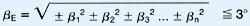
Joints with the same fork position in relation to their deflection plane have the same sign. (See fig 7).
In many cases, even with multiple joint shafts with physical deflection, sufficient compensation can be achieved. Please ask; we would be pleased to advise you.