
Repair & Replacement of Parts on Propeller Shafts
The UK’s Leading Independent Propshaft Specialists Since 1977
Technical Q&A's
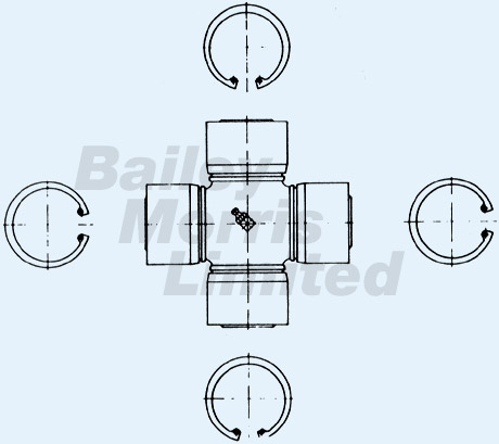
We strongly recommend not replacing damaged bearings individually as in most cases the pins on the universal joint will also be damaged. It is therefore advisable to replace only complete universal joint fittings (fig. 1). In the case of wear in the sliding profile, spinned shafts and hubs should always be replaced together. The wear limit for fast running shafts is achieved when play is perceptible in the installed position.
Dismantling a Joint
1. Remove all four circlips with circlip pliers.
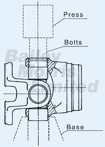
2. Push the universal joint and bushes to one side using a press. (see fig. 2a)
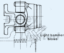
3. Clamp the projecting bush in a screw vice and withdraw the bush with light hammer blows on the fork (fig. 2b). Do not reuse bearing bushes with thin walls.
Assembling a Joint
1. Press in the bearing bushes exactly in line with their centrelines, without tilting them.
2. Fit circlips so that the universal joint can be easily removed. To achieve this, circlips of various thickness are used and if absolutely necessary a thicker circlip can be ground to the required dimension. The clearance at the ends of the pins should be adjusted so that the bending moment of the flange in both axes does not exceed 4Nm, without letting the flange drop down on its own accord.
3. Check that the joint runs true. To do this, mount the propeller shaft on the flange fitting and check the tube with a dial gauge. Maximum permissible runout is 0.1mm. For running speeds under 1500rpm this check will in most cases avoid the need for balancing and for speeds above 1500rpm it considerably shorten the balancing process.
In the case of motor vehicles, the running speed is generally above 1500rpm. Propeller shafts for this application must be dynamically balanced. The balancing speed should always be 10 – 15% above the maximum speed occuring in service.
The acceptable balance is laid out in DIN ISO 1940.


